To determine all critical solar positions that must be shaded, the UV Indices of all solar positions over the user-defined target-shade area are identified using a UV Index algorithm proposed by Allaart et. al. This algorithm requires the following three parameters: (i) the solar zenith angle, (ii) the earth-to-sun distance, and (iii) the concentration of total ozone over the selected site. Other parameters such as ozone temperature, albedo, and site altitude are given constant values and have little expected error on the algorithm. The adopted algorithm is globally applicable, except for sites with high altitudes, using the equations below.
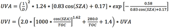
where UVA is Ultraviolet long wave (A) radiation
with a wavelength range from 320-400nm, UVI
Ultraviolet Index, D earth-to-sun
distance (au), SZA solar zenith angle
(°) and TOC total ozone concentration (DU).
For a specific site, solar positions are a function of
the site location, the day of the year, and the time of day. These three
parameters define the solar zenith angle, the
angle measured from directly overhead to the geometric center of the sun's
disc, as described using a horizontal coordinate system. This angle is established using well known astronomical algorithms.
Values for earth-to-sun distances are available from the National Aeronautics and Space Administration (NASA) for any user-defined time intervals here.
Data for total ozone concentration is obtained from the National Oceanic and Atmospheric Administration (NOAA) here.
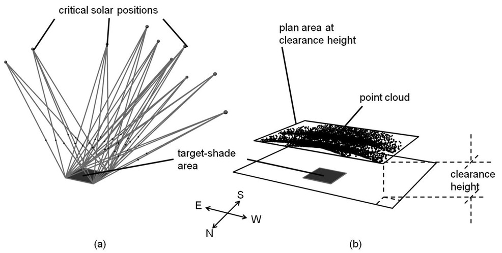
For each specific site, a series of vectors is constructed from a dense grid on a target-shade area to all critical solar positions (those with associated UV Indices above EPA-designated limits of 2.5). For clarity purposes, the figure (a) side below illustrates only the vectors going from a limited number of solar positions to the target-shade area (dark gray square). A point cloud is then defined by those points that lie on these vectors and that intersect a specified horizontal clearance plane, positioned parallel with the plane defined by the target-shade area. The height of this horizontal clearance plane (typically in the order of 2.8m to 5m) allows users to comfortably enter and operate beneath the shell. The (b) side of the figure shows the complete point cloud and the clearance plane. The obtained point cloud defines the contour of the plan area at clearance height. The cloud, while contained by an irregular shape, can be included by a variety of contour forms, as long as all cloud points are encompassed within the contour. A rectangular contour is selected below to contain the point cloud, thereby defining the approximate plan area of the eventual structure at the specified clearance height.
Reference:
Allaart M., van Weele M., Fortuin P., Kelder H. (2004). 'An empirical model to predict the UV-index based on solar zenith angles and total ozone.' Meteorological Applications, 11, pp 59-65. http://journals.cambridge.org/action/displayAbstract;jsessionid=4B1DD4F75F6B965A8E25BA5602F01CCD.journals?fromPage=online&aid=212305